 |
CustusX
2023.01.05-dev+develop.0da12
An IGT application
|
|
CustusX
2023.01.05-dev+develop.0da12
An IGT application
|
This page describes the CustusX way of handling coordinate systems. A basic knowledge of linear algebra and geometry is assumed. A coordinate system can also be called a space or frame. Space will be preferred here.
A space always has an ID. It is defined in terms of one other space, called its parent space. The origin and coordinate axes of the space is defined in the parent space. The origin and coordinate axes are concatenated into a 4x4 affine matrix. Spaces that are connected through a chain of references are connected. Otherwise they are unconnected and need a registration in order to be connected.
A point or vector p in space q are denoted
p_q
Space q has a parent space r. The affine matrix, or transform, M relating the two spaces are denoted
q_M_r (or qMr)
q_M_r is defined such that a point p_r in the parent space premultiplied with q_M_r yields the same point p_q represented in space q:
p_q = q_M_r * p_r
The multiplication here is done using homogenous coordinates, where a point is [x,y,z,1] and a vector is [x,y,z,0].
All computations are performed in millimeters and radians! File storage also use millimeters, but use degrees instead of radians.

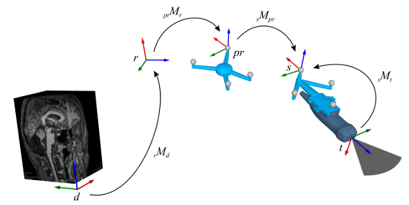
The basic spaces are reference and patient reference, representing respectively the virtual and physical world. When these two spaces have a valid relation, through the prMt transform, the system is properly set up for navigation. Tracking tools move relative to the patient reference, while data (CT, MR, US etc) are defined relative to the reference.
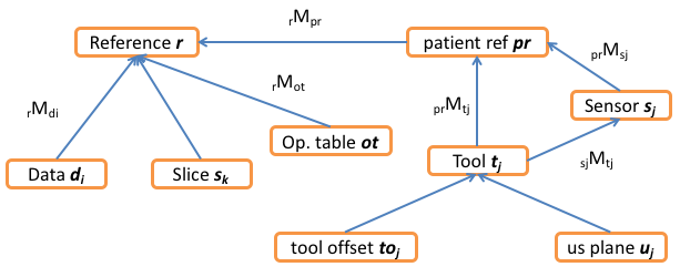
This figure shows all the major spaces in CustusX. They are described in the table below. Some spaces have a subscript; This means that there are several of them. See also Probe Spaces .
| Name | ID | Description |
|---|---|---|
| reference | r | The basic space that connects everything. Has no parent space. |
| patient reference | pr | A physical space, usually the reference tool. When rMpr is defined, the system is said to be patient registered, meaning image spaces are connected to the navigation tools. |
| data i | d_i | Each Data (Image or Mesh or other) has an associated space d_i. In simple cases, it has the reference space as its parent space, but it might also have another data space as parent space. This gives the ability to describe a tree of data spaces. The transform rMd_i is always stored in Data, regardless of the value of the parent space. |
| tool j | t_j | Each Tool has a space t that defines its position. The origin is usually the tool tip, this may vary for ultrasound probes. |
| tool offset j | to_j | Tools can have a virtual offset along its local z axis. The space thus translated is denoted to. |
| us plane j | u_j | See Probe Spaces . |
| sensor j | s_j | Tools usually have a tracking sensor attached that communicates with the tracking system. The local sensor space is denoted s. The transform sMt is the Tool calibration. |
| slice k | s_k | During slicing (for display in a 2D View) a space s is defined. The xy-plane of this space is the slice plane. It is defined with r as the parent space. (The s identifier is used for two different spaces, slice and sensor. This is unfortunate, but the two spaces are used in different contexts) |
| operating table | ot | The operating table is a concept which is representing an operating table with an up direction in the reference space. The table up direction can be set in the preferences. Different functionality can be set to depend on the table direction. See the Operating table for more details. |
The following table describes som important transforms, i.e. relations between two spaces:
| Name | ID | Description |
|---|---|---|
| Patient Registration | prMt | The Patient Registration connects the physical and virtual worlds, and is required in order to do navigation in the OR. This transform is acquired using a Patient Registration Procedure. |
| Tracking Raw data | prMs | Raw position data received from the tracking system. |
| Tool Calibration | sMt | Applied on top of the raw tracking position in order to find the position and orientation of the tool. This transform is either set from the tool producer or determined though a calibration procedure. |
| Data Position | rMd | Position of Data. Used throughout the system. |
| Tool Position | prMt | Position of Tool. Used throughout the system. |
| Operating table | rMot | The orientation of the operating table in the reference space. |
The following figure shows an example of two tools, one pointer and one probe. Both are related to the patient reference through the sMt transform.
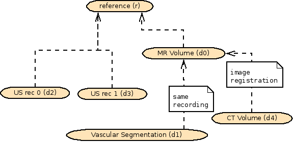
Although all Data objects are defined relative to the reference space, they also have a parent space. This allows hierarchical data structures. The parent relation is taken into account when performing registration.
The following figure shows a case where some Data has a parent space different from the reference space. One MR volume exists, and some vascular structures are segmented out from that volume and imported as a separate Data object (a Mesh). For consistency, the new Data have the MR as the parent frame.
The CT volume is imported separately, but is at some point image-registered to the MR volume. In the process, the parent frame is changed to the MR volume.
qMr) are implemented using cx::Transform3D. The internal representation is a 4x4 matrix. cx::Transform3D contains helper methods vec(cx::Vector3D) and coord(cx::Vector3D) that transforms the vector or point, respectively.Both cx::Transform3D and cx::Vector3D are based on the Eigen library.
The class CoordinateSystemHelpers provides some nice utility functions.
 1.8.11
