 |
Fraxinus
18.10
An IGT application
|
|
Fraxinus
18.10
An IGT application
|
The Ultrasound probe is defined as a special Tool with an attached Ultrasound video source and a sector definition. The following components form part of the probe definition in CustusX:
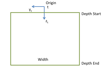
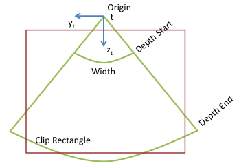
usprobe in the Tool File setup .The probe sector geometry is defined by the following properties:
| Name | Description |
|---|---|
| Type | sector or linear. |
| Origin | Position of geometry origin in the US image. This is always the origin of the tool space t. |
| Width | Angle for sector, mm for linear. |
| Depth Start/End | Defining the extent of the sector either radially from the origin (sector) or along the tool z axis (linear). For sector probes the Depth Start is zero, and nonzero for curvilinear probes. |
| Clip Rectangle | An additional constraint that can be added in the case that some parts of the sector is obfuscated by other information on the US scanner. |
| Image properties | Height/width and spacing (i.e. pixel size) of the video image. |
The two images show the probe definitions for linear and sector/curvilinear probes, respectively:
The probe configurations are stored in the file config/tool/ProbeCalibConfigs.xml.
The configurations here are used when no other information is available, i.e. when the connection to the US scanner is through a video grabber with no transfer of probe information. Any probe information received from the scanner will override the file configuration.
In order to connect the probe definition in the Probe Calibration Configuration File with the Tool File setup , these tags must correspond:
| tool file | ProbeCalibConfigs.xml |
|---|---|
| instrument/scannerid | USScanner/Name |
| instrument/id | USScanner/USProbe/Name |
Below are examples of corresponding files:
Tool File:
  <instrument>
    <type>usprobe</type>
    <id>L14-5</id>
    <scannerid>Ultrasonix</scannerid>
    ...
  </instrument>
ProbeCalibConfigs.xml:
        <USScanner>
            <Name>Ultrasonix</Name>
            <USProbe>
                <Name>L14-5</Name>
                ...
            </USProbe>
        </USScanner>
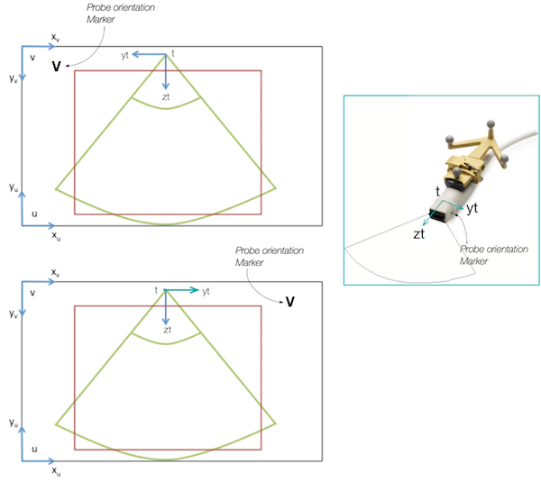
This table extends the one in Coordinate Systems with probe-specific spaces. They relate the US video image to the Tool using the Probe sector geometry .
| Name | ID | Description |
|---|---|---|
| tool | t | Space of the physical probe, relates the probe to the rest of the system. Origin is defined at probe sector apex, see Probe sector geometry. |
| image lower left | u | US video image. Origin lower-left corner, units mm. |
| image upper left | v | US video image. Origin upper-left corner, units mm. |
| image pixel | p | US video image. Origin upper-left corner, logical units (pixels). |
 1.8.11
